CHAPTER 4: DIGITAL LOGIC
Basic Revision At Logic Gate
Digital systems are said to be constructed by using logic gates. These gates are the AND, OR, NOT, NAND, NOR, XOR gates.
AND
OR


NOT
NAND


NOR


XOR
The 'Exclusive-NOR' gate circuit does the opposite to the OR gate.


Basic Combination Circut
There were three ways we can use to do a combination circut:
1) Truth table
Truth table helps we to understand the inputs of logic gate, We can know what the input and output
The gate input(s) are shown in the left column(s) of the table with all the different possible input combinations. This is normally done by making the inputs count up in binary.

2) Graphical Symbols
This is a graphic symbols that we use to present the operation of logic gate.

3)Boolean equation
Description of the Laws of Boolean Algebra
(1) Two separate terms NOR´ed together is the same as the two terms inverted (Complement) and AND´ed for example, A+B = A. B.
- Annulment Law – A term AND´ed with a “0” equals 0 or OR´ed with a “1” will equal 1.
-
- A . 0 = 0 A variable AND’ed with 0 is always equal to 0.
- A + 1 = 1 A variable OR’ed with 1 is always equal to 1.
- Identity Law – A term OR´ed with a “0” or AND´ed with a “1” will always equal that term.
-
- A + 0 = A A variable OR’ed with 0 is always equal to the variable.
- A . 1 = A A variable AND’ed with 1 is always equal to the variable.
- Idempotent Law – An input that is AND´ed or OR´ed with itself is equal to that input.
- A + A = A A variable OR’ed with itself is always equal to the variable.
A . A = A A variable AND’ed with itself is always equal to the variable.
- Complement Law – A term AND´ed with its complement equals “0” and a term OR´ed with its complement equals “1”.
A . A = 0 A variable AND’ed with its complement is always equal to 0.
A + A = 1 A variable OR’ed with its complement is always equal to 1.
- Commutative Law – The order of application of two separate terms is not important.
- A . B = B . A The order in which two variables are AND’ed makes no difference.
- Double Negation Law – A term that is inverted twice is equal to the original term.
A + B = B + A The order in which two variables are OR’ed makes no difference.
- A = A A double complement of a variable is always equal to the variable.
Example: Using the above laws, simplify the following expression: (A + B)(A + C)
"de Morgan´s Theorem" There are two “de Morgan´s” rules or theorems,
(1) Two separate terms NOR´ed together is the same as the two terms inverted (Complement) and AND´ed for example, A+B = A. B.
(2) Two separate terms NAND´ed together is the same as the two terms inverted (Complement) and 'OR´ed for example, A.B = A +B.
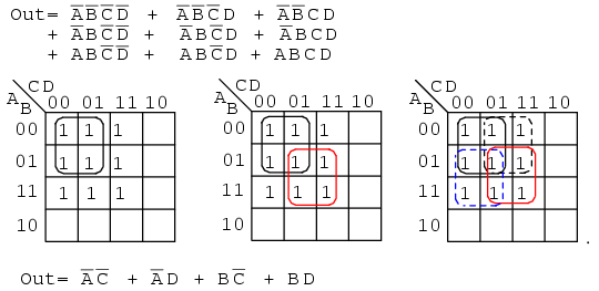
Karnaugh Map
A Karnaugh Map is a grid-like representation of a truth table. It is really just another way of presenting a truth table, but the mode of presentation gives more insight


Note the following about the four variable Karnaugh Map.
There are 16 cells in the map. Anytime you have N variables, you will have 2N possible combinations, and 2N places in a truth table or Karnaugh Map.
Imagine moving around in the Karnaugh Map. Every time you cross a horizontal or vertical boundary one - and only one - variable changes value.
The two pairs of variables - WX and YZ - both change in the same pattern.

Example:

Universal Gates
Universal gates that caan be used to implement any gates like AND, OR ,NOT, and any combination of gates. NAND and NOR are the universal gates.
NAND


List of NAND gates.

NOR

There not many different between NAND and NOR gates.
The Logic NOR Gate or Inclusive-NOR gate is a combination of the digital logic OR gate with that of an inverter or NOT gate connected together
The Logic NOR Gate or Inclusive-NOR gate is a combination of the digital logic OR gate with that of an inverter or NOT gate connected together
The NOR (Not – OR) gate has an output that is normally at logic level “1” and only goes “LOW” to logic level “0”
There are have a few ways to show the input:
2-input NOR Gate


No comments:
Post a Comment