Thursday, December 15, 2016

INTRODUCTION

When we are about want to buy a new personal computer, normally we will find out the details on the computer. The things we consider before buying a computer:
  • Computer brand.
  • Internal software.
  • Price. 
In this blog, we want to explore what is computer. How computer works and what system it use..

Chapter 10


CACHE


Pronounced cash, a special high-speed storage mechanism. Cache can be either a reserved section of main memory or an independent high-speed storage device. Two types of caching are commonly used in personal computers: memory caching and disk caching.

Elements of cache addresing:
- cache address
- mapping function
- replacement algorithm
- write policy


location of memory:
- internal & external in computer
Internal:
cache is internal form memory,
• External :
Storage devices (paper tape, cards, tapes, discs, flash cards, etc.)

Capacity
• Word size 
The natural unit of organisation and Typically number of bits used to represent an integer in the processor
 • Number of words 
Most memory sizes are now expressed in bytes . Most modern processors have byte-addressable memory but some have word addressable memory .Memory capacity for A address lines is 2A addressable units  

Unit of Transfer
• Internal :Usually governed by data bus width 
• External :Usually a block which is much larger than a word (typical disk 512 - 4096 bytes)
 • Addressable unit :Smallest location which can be uniquely addressed .Some systems have only word addressable memory while many have byte addressable memory .A block or even cluster of blocks on most disks 

Acces method


• Sequential : Start at the beginning and read through in order. Access time depends on location of data and previous location.. e.g. tape
 • Direct : Individual blocks have unique address ,Access is by jumping to vicinity plus sequential search. Access time depends on location and previous location — e.g. disk
• Random: Individual addresses identify locations exactly .Access time is independent of location or previous access —e.g. RAM 
• Associative :Data is located by a comparison with contents of a portion of the store .Access time is independent of location or previous access. All memory is checked simultaneously; access time is constant — e.g. cache 

• Three performance parameters: 
  — Access time 
  — Cycle Time 
  — Transfer Rate

Physical type:
• Semiconductor — RAM (volatile or non-volatile)
 • Magnetic Surface Memory — Disk & Tape 
• Optical — CD & DVD
 • Others — Magneto-optical — Bubble — Hologram 

Character

• Volatility: Does the memory retain data in the absence of electrical power?
• Decay: Ranges from tiny fractions of a second (volatile DRAM) to many years (CDs, DVDs)
• Erasable:Can the memory be rewritten? If so, how fast? How many erase cycles can occur? 
• Power consumption

Organization 

• Physical arrangement of bits into words • Not always obvious, e.g., interleaved memory (examples later)


Memory Hierarchy 

• For any memory:  How fast? How much? How expensive? 
• Faster memory => greater cost per bit 
• Greater capacity => smaller cost / bit 
• Greater capacity => slower access 
• Going down the hierarchy: Decreasing cost / bit [Increasing capacity ] Increasing access time .Decreasing frequency of access by processor

Cache memory Principals


• If data sought is not present in cache, a block of memory of fixed size is read into the cache
 • Locality of reference makes it likely that other words in the same block will be accessed soon


Types of memory

)Real memory
= Main memory
)Virtual memory:
=memory on disk


Memory Hierarchy

 • Registers — In CPU
 • Internal or Main memory — May include one or more levels of cache (“RAM”)
• External memory — Backing store 

Mapping Function 

• There are fewer cache lines than memory blocks so we need , An algorithm for mapping memory into cache lines. A means to determine which memory block is in which cache line
 • Example elements: — Cache of 64kByte /Cache block of 4 bytes – i.e. cache is 16k (214) lines of 4 bytes/16MBytes main memory/ 24 bit address (224=16M.


Chapter 9


Pipelining

Pipelining is an implementation technique where multiple instructions are overlapped in execution. The computer pipeline is divided in stages. Each stage completes a part of an instruction in parallel. The stages are connected one to the next to form a pipe - instructions enter at one end, progress through the stages, and exit at the other end.

Datapath instruction:

 R-type
 J-type

5 Component of computer.


▸ Processor (CPU): the active part of the computer that does all the work (data manipulation and decision-making) 
▸ Datapath: portion of the processor that contains hardware necessary to perform operations required by the processor (the brawn) 
▸ Control: portion of the processor (also in hardware) that tells the datapath what needs to be done (the brain)

5 Stage of Datapath
▸ Stage 1: Instruction Fetch
▸ Stage 2: Instruction Decode
▸ Stage 3: ALU (Arithmetic-Logic Unit)
▸ Stage 4: Memory Access
▸ Stage 5: Register Write 

Stage 1:
 Instruction Fetch. there are no matter what the instruction, the 32-bit instruction word must first be fetched from memory (the cache-memory hierarchy)  it also, this is where we Increment PC (that is, PC = PC + 4, to point to the next instruction: byte addressing so + 4)

▸ Stage 2: 
Instruction Decode.  upon fetching the instruction, we next gather data from the fields (decode all necessary instruction data) .First, read the opcode to determine instruction type and field lengths ,second read in data from all necessary registers 
▸ for add, read two registers ; for addi, read one register ; for jal, no reads necessary
▸ Stage 3:
 ALU (Arithmetic-Logic Unit). The real work of most instructions is done here: arithmetic (+, -, *, /), shifting, logic (&, |), comparisons (slt).. loads and stores? ▸ lw $t0, 40($t1)  the address we are accessing in memory = the value in $t1 PLUS the value 40 

▸ Stage 4: Memory Access . Actually only the load and store instructions do anything during this stage; the others remain idle during this stage or skip it all together ,since these instructions have a unique step, we need this extra stage to account for them ,as a result of the cache system, this stage is expected to be fast 

▸ Stage 5: Register Write.  Most instructions write the result of some computation into a register Examples: arithmetic, logical, shifts, loads, slt .. Stores, branches, jumps don’t write anything into a register at the end ▸ these remain idle during this fifth stage or skip it all together .


Steps Of Datapath


Datapath walkthrough

add $r3, $r1, $r2 # r3 = r1 + r2 
▸ Stage 1: fetch this instruction, increment PC
 ▸ Stage 2: decode to determine it is an add, then read registers $r1 and $r2
  ▸ Stage 3: add the two values retrieved in Stage 2 
   ▸ Stage 4: idle (nothing to write to memory)
    ▸ Stage 5: write result of Stage 3 into register $r3 


sw instruction

sw $r3, 17($r1) # Mem[r1+17] = r3 
Stage 1: fetch this instruction, increment PC 
 Stage 2: decode to determine it is a sw, then read registers $r1 and $r3
  Stage 3: add 17 to value in register $r1 (retrieved in Stage 2) to compute address
  Stage 4: write value in register $r3 (retrieved in Stage 2) into memory address computed in Stage 3  Stage 5: idle (nothing to write into a register) 


Before pipeline..

• Single-cycle control: hardwired – Low CPI (1) – Long clock period (to accommodate slowest instruction) 
• Multi-cycle control: micro-programmed – Short clock period – High CPI 

Pipeline 
• Start with multi-cycle design 
• When insn0 goes from stage 1 to stage 2 … insn1 starts stage 1
 • Each instruction passes through all stages … but instructions enter and leave at faster rate 


Pipeline Terminology 
• Pipeline Hazards – Potential violations of program dependencies .Must ensure program dependencies are not violated 
• Hazard Resolution – Static method: performed at compile time in software .Dynamic method: performed at runtime using hardware – Two options: Stall (costs perf.) or Forward (costs hw.) 
• Pipeline Interlock – Hardware mechanism for dynamic hazard resolution – Must detect and enforce dependencies at runtime


For details  ðŸ‘‰ click here


CHAPTER 6

Language Of Computer - MIPS

In MIS there have few stages. Assembly languages, Instruction, Assembly operands, Data transfer and Decision instruction.

Assembly language:

The computer job is execute lots of instruction. The set of instruction a particular CPU implement is an Instruction Set Architecture(ISA).

What is ISA?

The instruction set, also called instruction set architecture (ISA), is part of a computer that pertains to programming, which is basically machine language. The instruction set provides commands to the processor, to tell it what it needs to do.
Ex: Intel 80x86 (pentium 4).

🔸Early trend: They idea is want to add more instruction to CPU.

🔸RISC Philosophy: Change their system, It redeuse the instruction, but it increase the speed. It wants keep small and simple.


MIPS Architecture:

MIPS - Microprocessor without Interlocking Pipeline Stages.
MIPS processor: Originally used in Unix workstations, now mainly used in small devices. ( Play Station, routers, printers, robots, cameras ).

Assembly Variable is register, Register is a limited number of a special locations built in software. Register is a very fast in software. Register is a permenant number in system. It only have 32 register in MIPS.
Register is a number from 0 to 31

Ex:
   # sum = x + y
    lw      $t0, x          # Load x from memory into a CPU register
    lw      $t1, y          # Load y from memory into a CPU register
    add     $t0, $t0, $t1   # Add x and y
    sw      $t0, sum        # Store the result from the CPU register to memory

Another ways to make code is comments
[#] is used for end line in MIPS format. 

In assembly language, each statements called instruction.

 
This operation using MIPS format.


in this case, we should know the formats its use.

Register zero, can use 2 code. Zero & 💲0,

Immediates, they are no subract.

Assembly Operands:
=Memory containe such data structure. Data transfer between register and memory.

Memory to Reg: specify 2 things, register and Memory address.  REMEMBER(Load from memory)
                          >Register contain a pointer to memory.
                          > A numerical offset(in bytes)


                 ← Data flow
ex: lw 💲t0, 12(💲s0)

💲s0 called the base register,
12 is offset,                                               #### constant know at assembly time.

Reg to Memory

MIPS instruction name is sw          
 data flow ➡
sw 💲t0,12(💲s0)                                        ###store into memory.


Memory Organization

Viewed as a large single-dimension array with access by address.
In memory:

   
Big Little Indian

Big Endian
In big endian, you store the most significant byte in the smallest address. Here's how it would look:

AddressValue
100090
1001AB
100212
1003CD
Little Endian
In little endian, you store the least significant byte in the smallest address. Here's how it would look:


A
ddressValue
1000CD
100112
1002AB
100390

Notice that this is in the reverse order compared to big endian. To remember which is which, recall whether the least significant byte is stored first (thus, little endian) or the most significant byte is stored first (thus, big endian).


Wednesday, December 14, 2016

CHAPTER 8 : MIPS INSTRUCTION FORMAT AND ADRESSING MODE


INSTRUCTION FORMATS
  • There are three types of instruction format : Register Type (R-Type) , Immediate Type (I-Type) and Jump Type (J-Type).


Register Type (R-Type)
  • ·        This group contains all instruction that do not require an immediate value , target offset ,memory address displacement , or memory address to specify an operand.
  • ·        This includes arithmetic and logic with all operands in registers , shift instruction , and register direct jump instruction (jal and jr)
  • ·        All R-type instruction use opcode 000000

6
5
5
5
5
6
Op
Operation Code
Rs
Source register specifier
Rt
Target register specifier
Rd
Destinantion register specifier
Shamt
Shift amount
Funct
Function field


Immediate Type (I-Type)
·        This group includes instruction with an immediate operand , branch instruction , and load and store instruction
·        In the MIPS architecture , all memory accesses are handled by the main processor , so coprocessor load and store instruction are includes in this group
·        All opcodes except 000000 , 00001x , and 0100xx are used for I-type instruction
6
5
5
16
Op
Operation Code
Rs
Source register specifier
Rt
Target register specifier or branch condition
Immediate
Immediate , branch displacement or address displacement

Jump Type (J-Type)
·        This group consists of the two direct jump instructions ( j and jal )
·        These instructions require a memory address to specify their operand
·        J-type instructions use opcodes 00001x
6
26
Op
Operation Code
Target
Target address

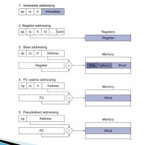
ADDRESSING MODES
Addressing modes are the ways of specifying an operand or a memory address . The MIPS addressing modes can be grouped into 5 types.
1.      Register Addressing : A source or destination operand is specified as content of one of the registers $0-$31
2.      Immediate Addressing : A numeric value ambedded in the instruction is the actual operand
3.      PC-Relative Addresssing : A data or instruction memory loacation is specified as an offset relative to the incremented PC
4.      Base Adressing : A data or instruction memory location is specified as a signed offset from a register
5.      Pseudo-direct Addressing : The memory address is (mostly) embedded in the instructions


Register Addressing
·        Register addressing is the simplest addressing mode
·        In this category , both operands are in a register . Instructions will be executed faster in comparison with other addressing modes because they does not involves with memory access
·        Consider the following instruction :
Add $t0 , $t1 , $t2

Where ; $t0 = rd
             $t1 = rs
             $t2 = rt
Thus ; $t0 = $t1 + $t2


Immediate Addresssing
·        In immediate addressing , the operand is a constant within the encoded instruction
·        Similar to register addressing , instruction will be execute faster because it does not involve memory access . However , the size of operand is limited to 16 bits
·        The jump instruction format also falls under immediate addressing , where the destination is held in the instruction
·        Consider the following instruction :
Addi $t1 , $t1 , 1

Where ; $t1 = rd
             $t1 = r1
                1 = immediate value
Thus; $t1 = $t1 + $1


Base Addressing
·        Base addressing is also known as indirect addressing , where a register act as a pointer to an operand located at the memory location whose address is in the register
·        The register is called base that may point to a structure or some other collection of data and immediate value is loaded at a constant offset from the beginning of the structure . The offset specifies how far the location of the operand data from the memory location pointed by the base
·        The address of the operand is the sum of the offset value and the base value (rs) . However , the size of operand is limited to 16 bits because each MIPS instruction fits into aword
·        The offset value is a signed number which is represented in a two’s complement format . Therefore , offset value can also be a negative value
·        Consider the following instruction:
Lw $t1 , 4($t2)

Where $t1 = rs
           $t2 = base (memory address)
             4 = offset value
Thus; $st1 = Memory [$t2 + 4]


PC-Relative Addressing
·        PC-relative addressing is usually used in conditional branches.PC refers to special purpose register , Program counter thet stores the address of next instruction to be fetched
·        In PC-relative addressing , the offset value can be an immediate value or an interpreted label value
·        The effective address is the sum of the Program Counter and offset value in the instruction . The effective address determines the branch target
·        PC-relative addressing implements position –independent codes.Only a small offset is adequate for shorter loops
·        Consider the following insruction:
Beqz $t0 , strEnd

Where ; $t0 = rs
              100 = offset
Thus ; if ($t1 == 0) goto PC + 4 + (4*2)
·        Example of PC relative addressing
Address
Instruction
Note
40000008
Subi $t0 , $t0
Binary code to beqz $t0 ,
strEnd is 0x110000004 , which means 2 instruction .

PC = 0 x 4000000C
PC + 4 = 0 x 40000010
Add 4*2 = 0 x 00000008
Effectives Address = 0 x 40000018
4000000C
Beqz $t0 , label
40000010
Subi $t0 , $t0
40000014
Subi $t0 , $t0
40000018
strEnd :
subi $t0 , $t0
4000001C
Subi


Pseudo-Direct Addressing
·        Pseudo-Direct addressing is specifically used for J-type instructions , j and jal . The instruction format is 6 bits of opcode and 26 bits for the immediate value (target)
·        In Pseudo-Direct addressing , the effective address is calculated by taking the upper 4 bits of the Program Counter (PC) ,concatenated to the 26 bit immediate value , and the lower 2 bits are 00.
·        Consider the following instruction :
J label
The implementation of the instruction is best described using the following operation :
Bits 31-28
Bits 27-2
Bits 1&0
PC: 01111
Immediate :
Shift :
01 0100 0101 0000 1011 1101 0110
00

00
Effective 0111
Address
01 0100 0101 0000 1011 1101 0110
00